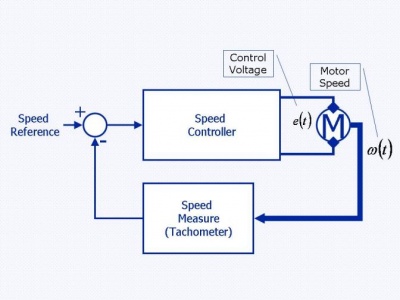
Motore DC: Questo articolo mostra come creare una procedura per l'identificazione di un motore DC a magneti permanenti mirato al controllo digitale della coppia.
Vengono utilizzati L298 (vedi il datasheet) (un driver "dual full-bridge" progettato per accettare livelli logici TTL e pilotare relè, solenoidi, DC e motori passo passo) e ADM3202/ADM3222/ADM1385 (transceivers, ideali per batteria dei portatili).
L'applicazione e' divisa in due parti:
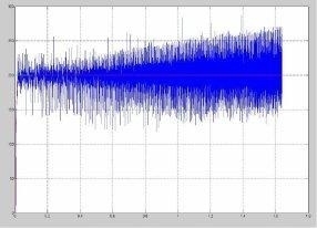
- Nella prima parte, il dsPIC esegue un campionamento simultaneo di tensione e corrente ed invia i dati attraverso il bus seriale ad un PC remoto;
- Nella seconda parte, il controllore PI, progettato sul modello identificato, e' utilizzato per controllare la corrente (direttamente) e la coppia (indirettamente) con appropriate caratteristiche di forza.
Sul lato del PC, i dati sono processati con un software specifico per il sistema di identificazione.
I metodi applicati sono: il metodo Subspaces (con dati generici I/O); il metodo PEM (per raffinare il modello) e analisi del residuo (per convalidare il modello).
Clicca qui per vedere 
Motore DC: Identificazione I-V e controllo di coppia - un pezzo del codice utilizzato
int main ( void )
{
unsigned char ias[dim_data];
//unsigned char vas[dim_data];
UART1_config(); // Initialize the UART module to receive data.
TRISEbits.TRISE2 = 0; // Enable signal on RE2.
iav = ias;
//vav = vas;
PORTEbits.RE2 = 0; // H-Bridge disabled.
st[0] = 0xAA; // Start Signal.
st[1] = 0xBB;
st[2] = 0xCC;
st[3] = '\0';
send_by_UART1((unsigned int *)st,3); // Characters transimitted in hex.
while(1)
if(icount > 25600)
stop_simulation();
return 0;
}
/****** START OF INTERRUPT SERVICE ROUTINES *********/
/* Replace the interrupt function names with the */
/* appropriate names depending on interrupt source. */
/* The names of various interrupt functions for */
/* each device are defined in the linker script. */
/* Interrupt Service Routine 1 */
/* No fast context save, and no variables stacked */
/****************************************************/
/* This is: ADC1 ISR */
void __attribute__((__interrupt__)) _ADC1Interrupt(void)
{
/* Clear the A/D Interrupt flag bit or else the CPU will
keep vectoring back to the ISR*/
IFS0bits.AD1IF = 0;
//if(switch_adc == 0){
// Corrente di armatura (output):
if(ADC1BUF0 > c_danger) stop_simulation();
iav[icount] = ADC1BUF0/2; // ATT!!! scale-factor = 2...
errc0 = 200-ADC1BUF0;
//errc0 = 0;
uin1 += (float)errc1*0.005; // Regulator. Double: [V], [A] u1 +=2e-3*err1
errc1 = errc0;
DCpwm = ( ((long int)uin1)-35 )*5;
DCpwm = (DCpwm<50)?1:( (DCpwm>800)?800:DCpwm );
*(&PDC1+2) = DCpwm*2-1; // Set DC -> Vmax = 5.7V , Vmin=1V
//}
/*
if(switch_adc == 1) // Tensione di armatura (input):
// if( ADC1BUF0 > c_lim ) stop_simulation();
vav[icount++] = ADC1BUF0; // ATT!!! scale-factor = 2...
*/
icount++;
//switch_adc ^= 1;
}
/* This is: UART1 receive ISR */
void __attribute__((__interrupt__)) _U1RXInterrupt(void)
{
unsigned long int x,y,z;
IFS0bits.U1RXIF = 0;
int i=0;
for(i=0; i<4 && DataRdyUART1();i++)
Buf[i] = ReadUART1();
/* Prompt: AA xx xx xx -> Turn on the real simulation and set the sample-time;
BB 00 00 00 -> Turn off the real simulation;
CC .. .. .. -> Start Control...
DD 00 xx xx -> New Duty Cycle for the PWM Module;
EE .. .. .. -> Nothing;
FF xx xx xx -> Nothing; */
switch (Buf[0])
{
/*******************************/
case 0xAA:
if(PORTEbits.RE2 != 1){
reset_counters();
ADC1_config(); // Configure the A/D converter.
x = Buf[1];
y = Buf[2];
z = Buf[3];
x = (x<<16) + (y<<8) + z;
if(x!=0)
TIMER23_config(x); // Timer23(32 bit) configuration.
else
TIMER23_config(Tsample);
Tpwm = Tsample; // Calculate the PWM period.
PWM_config((unsigned int)DCpwm,Tpwm); // Configure the PWM module.
st[0] = (x>>16) & 0x00FF;
st[1] = (x>>8) & 0x00FF;
st[2] = x & 0x00FF;
send_by_UART1((unsigned int *)st,3);
while(BusyUART1());
PORTEbits.RE2 = 1; // H-Bridge enabled.
} break;
/*******************************/
case 0xBB:
stop_simulation();
break;
/*******************************/
case 0xCC: // Start Control...
T2CONbits.TON= 1; // Turn on Timer23.
AD1CON1bits.ADON = 1; // Turn on ADC1
PTCONbits.PTEN= 1; // Turn on PWM.
break;
/*******************************/
case 0xDD:
x = (Buf[2]<<8) + Buf[3];
if(x > 0)
DCpwm = (unsigned int)x;
if(AD1CON1bits.ADON == 0){
st[0] = (char) ((DCpwm>>8) & 0x00FF);
st[1] = (char) (DCpwm & 0x00FF);
st[2] = '\0';
send_by_UART1((unsigned int *)st,2);
while(BusyUART1());
}
break;
/*******************************/
case 0xEE:
break;
/*******************************/
case 0xFF: // Duty Cycle settings.
break;
/*******************************/
default:
if(AD1CON1bits.ADON == 0){
char s[5];
s[0] = (char) 0xFF;
s[1] = (char) 0xFF;
s[2] = (char) 0xFF;
s[3] = (char) 0xFF;
s[4] = '\0';
send_by_UART1((unsigned int *)s,4);
while(BusyUART1());
}
/*******************************/
}
}
Per avere tutto il codice, clicca qui.
Repost: 13 Giu 2008