Questo articolo mostra un metodo per l'acquisizione dell'immagine da una fotocamera CMOS dotata di interfaccia seriale utilizzando FLEX.
FLEX è una scheda per sistemi modulari embedded che utilizza le potenzialità dei microcontrollori dsPIC (R) DSC prodotti da Microchip. E' una scheda ideale per sviluppare applicazioni real-time perché il microcontrollore dsPIC33FJ256MC710 supporta kernel real-time come Erika Enterprise prodotto da Evidence Srl.
Il software è diviso in due: un'applicazione MPLAB per essere caricata sul microcontrollore (dsPIC33FJ256MC710) di FLEX e un'applicazione Win32 per l'acquisizione dei dati seriali e per la visualizzazione delle immagini.
Per l'applicazione PC Side le richieste sono: il programma utilizza cygwin1.dll, che può essere condiviso attraverso le finestre "PATH environment variable" o può essere posizionato in "executable directory". Il programma deve essere eseguito in Microsoft/Cygwin.
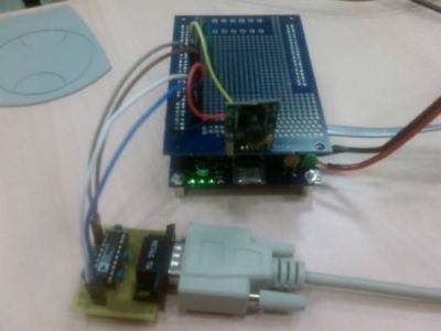
I requisiti per l'applicazione Flex Side sono: FLEX Base Board (Light o Full), PCB per "serial RS232 voltage conversion", condensatori e connettori, un modulo CAMVGA100. Utilizzando il "project Wizard", create un nuovo progetto MPLAB nella directory Flex-side e costruite un file eseguibile; o utilizzando "$ makefile" per creare il progetto. Poi, programmate il dispositivo microchip per mezzo di un programmatore ICD2.

Vediamo un pezzo del codice:
/************** MAIN ***********/
int main ( void )
{
unsigned char camok=0;
unsigned int i=0;
// Fcy/115200/16-1 = 5.78 -> 6
/* Clock setup for 40MIPS */
RCONbits.SWDTEN = 0;                    // Disable Watch Dog Timer
CLKDIVbits.DOZEN   = 0;
CLKDIVbits.PLLPRE  = 0;
CLKDIVbits.PLLPOST = 0;
PLLFBDbits.PLLDIV  = 76;				// to have Fcy = 39e6Hz...
while(OSCCONbits.LOCK!=1);            	/* Wait for PLL to lock */
//U1BRG=20;
//U1BRG=20; // BAUD_RATE = 115200
//U1BRG=41; // BAUD_RATE = 57600
U1BRG=62; // BAUD_RATE = 38400
//U1BRG=125; // BAUD_RATE = 19200
//U1BRG=253; // BAUD_RATE = 9600
UART1_Config(U1BRG);
//while(1)                                  //Loop forever
//{
//Main routine
//Loops forever detecting the baud rate from incoming UART data of 0x55
//and outputing a message each time the baud rate is calculated.
//SetupAutoBaud();                       //Set up UART1, IC1 and TMR3 for autobaud
//while(U1BRG == 0) {}                   //Wait for autobaud to complete
//BRate = ((unsigned )Fcy / 16) / (U1BRG + 1);   //See what baud rate is being used
//printf("Baud rate: %ld\r", BRate);  //Output text with the baud rate
//while(finish == 0);
//finish=0;
//Cam_TIMER89Config(152343);
//Cam_Sleep(76170);	//0.1sec
//IEC0bits.IC1IE = 0;           	//Clear Capture 1 interrupt enable
//IEC0bits.T3IE = 0;            	//Clear Timer 3 interrupt enable
//U1BRG_calcval = (unsigned int)(((SumOfBitTimes + 64) >> 7) - 1);
//UART1_Config( U1BRG_calcval );
//Cam_Sleep(152343);
//Cam_CloseTimer89();
//		ust[0] = (U1BRG>>8) & 0x00FF;
//		ust[1] = U1BRG & 0x00FF;
//		Send_by_UART1((unsigned int *)ust,2);
//		while(BusyUART1());		//Wait for transmission to complete
//		Send_by_UART1((unsigned int *)ust,2);
//		while(BusyUART1());		//Wait for transmission to complete
//ust[0] = 0xAA;
//ust[1] = 0xBB;
//ust[2] = 0xCC;
//ust[3] = 0xDD;
//Send_by_UART1((unsigned int *)ust,4);
//while(BusyUART1());		//Wait for transmission to complete
//break;
//}
//UART1_Config(259);
//ust[0]=0xAA;
//Send_by_UART1((unsigned int *)ust,1);
//while(BusyUART1());		//Wait for transmission to complete
//UART1_Config(62);
//UART1_Config(20);         // Initialize the UART module to receive and transmit serial data.
//UART1_Config(41);
Cam_Init();
//		while(1)
//		{
//			ust[0]=0xAA;
//			Send_by_UART1((unsigned int *)ust,1);
//			for(i=0;i<60000;i++);
//		}
//start1=1;
while(1)
{
if(start1)
{
start1=0;
camok = Cam_Synchronization( (float)Fcy );
if(camok)
{
ust[0]=0x12;
ust[1]=0x34;
//Send_by_UART1((unsigned int *)ust,2);
}
else
{
ust[0]=0xEE;
ust[1]=0xEE;
Send_by_UART1((unsigned int *)ust,2);
continue;
}
//if(!camok) continue;
camok = Cam_GetStream();
}
}
//CloseUART1();
//while(1);
return 0;
}
// void SetupAutoBaud(void) -> Read me: Set up the peripherals and interrupts to do baud rate detection
void SetupAutoBaud(void)
{
U1BRG = 0;                 //U1BRG initially unknown
U1MODE = 0x8820;           //Enable auto baud detection in UART
U1STA = 0x85D0;            //Set up rest of UART to default state with transmission enabled
ICCount = 0;               //Initialize the number of Capture events
IC1CON = 0x0000;           //Reset Input Capture 1 module
IC1CON = 0x0002;           //Enable Input Capture 1 module
IFS0bits.IC1IF = 0;        //Clear Capture 1 interrupt flag
IEC0bits.IC1IE = 1;        //Enable Capture 1 interrupt
T3CON = 0x0000;            //Timer 3 off
IEC0bits.T3IE = 0;         //Clear Timer 3 interrupt enable
T3Count = 0;               //Initialize the number of Timer 3 interrupts
PR3 = 0xffff;              //Timer 3 period is maximum
T3CON = 0x8000;            //Timer 3 on with 1:1 prescaler and internal clock
}
Per maggiori informazioni clicca qui.